Serving tech enthusiasts for over 25 years. TechSpot means tech analysis and advice you can trust.
When you buy through our links, we may earn a commission.
You might have a desktop PC at work, school, or home. You might use one to work out tax returns or play the latest games; you might even be into building and tweaking computers. But how well do you know the components that make up a PC? Take the humble motherboard – it sits there, quietly keeping everything running, and rarely gets the same attention as the CPU or graphics card.
Motherboards are remarkably important though, and full of really cool technology. So let's go all Grey's Anatomy, and dissect the motherboard – breaking down its various parts and seeing what each bit does!
TechSpot's Anatomy of Computer Hardware Series
You might have a desktop PC at work or home. You might use one to work out tax returns or play the latest games; you might even be into building and tweaking computers. But how well do you know the components that make up a PC?
Let us begin with the main role of a motherboard. In essence, it serves two purposes:
Provide electrical power to the individual components
Provide a route to allow the components to communicate with each other
There are other things a motherboard does (e.g. holds the components in place, or provides feedback as to how well everything is functioning) but the aforementioned aspects are critical to how a PC operates, that almost every other part that makes up the motherboard, is related to these two things.
Nearly every motherboard used in a standard desktop PC today will have sockets for the central processing unit (CPU), memory modules(nearly always a type of DRAM), add-in expansion cards (such a graphics card), storage, input/ouputs, and a means to communicate with other computers and systems.
Standard motherboards initially differ in terms of their size, and there are industry-wide standards that manufacturers tend to adhere to (and plenty of others that don't). The main sizes you're likely to come across are:
Standard ATX - 12 × 9.6 inches (305 × 244 mm)
Micro ATX - 9.6 × 9.6 inches (244 × 244 mm)
Mini ATX - 5.9 × 5.9 inches (150 × 150 mm)
You can see a far more comprehensive list on Wikipedia but we'll just stick to standard ATX for simplicity, because the differences generally lie in the number of sockets available to be powered and connected; a bigger motherboard permits more sockets.
But what exactly is a motherboard?
A motherboard is simply a big electronic printed circuit board, with lots of connectors to plug things into and hundreds, if not thousands, of feet of electrical traces that run between the various sockets. Theoretically, the board isn't needed: you could connect everything together by using a huge mass of wires. The performance would be terrible, though, as the signals would interfere with one another, and there would be notable power losses by using this method, too.
We'll begin our breakdown by using a typical ATX motherboard. The image below corresponds to an Asus Z97-Pro Gamer and its appearance, features, and functions can be found in dozens more like it.
The only problem with the picture (other than the motherboard being quite... umm... well, used) is that there are a lot of visible components, making it trickier to spot everything clearly.
Let's strip it all away and look at a simplified diagram to begin with (below).
That's better, but there is still a lot of sockets and connectors to talk about! Let's start near the top, with the most important one of all.
Wiring up the brains of a PC
The diagram has a structure labelled LGA1150. This is the name used by Intel to describe the socket used to hold many of their CPUs. The letters, LGA, stand for Land Grid Array, a common type of packaging technology for CPUs and other integrated circuits.
LGA systems have lots of little pins in the motherboard, or in a socket on the board, to provide power and communications to the processor. You can see them in the picture below:
The metal bracket holds the CPU in place but it's getting in the way of seeing the pins clearly, so let's move it to one side.
Remember the name for this? LGA1150. The number is for how many pins there are in this socket. We'll explore the connections for a CPU in another article, but for now we'll just point out that motherboards for other CPUs will have more or fewer pins.
In general, the more capable the CPU (in terms of number of cores, amount of cache, etc), the more pins will be found in the socket. A large number of these connections will be used to send and receive data to the next important feature on a motherboard.
Big brains need big memory
The sockets or slots that are always the closest to the CPU are those that hold DRAM modules, aka system memory. These are connected directly to the CPU and nothing else on the motherboard. The number of DRAM slots depend mostly on the CPU, as the controller for the memory is built into the central processor.
In the example we're looking at, the CPU that fits into this motherboard has 2 memory controllers, with each one handling 2 sticks of memory - hence there are 4 sockets in total. You can see that, on this motherboard, the memory sockets are colored in way to let you know which ones are managed by which controller. They're commonly called memory channels, so channel #1 handles two of the slots and channel #2 handles the other two.
For this particular motherboard, the colors of the slots can be a little confusing (and it certainly confused this author!): the two black slots are actually one each for the two memory controllers (and same for the grey ones). So the black slot closest to the CPU socket is channel #1, and the next black one is channel #2.
It's colored like this to encourage you use the motherboard in what is called dual memory channel mode - by using both controllers at the same time, the overall performance of the memory system is increased. So let's say you had two RAM modules, each one 8 GB in size. No matter what slots you put them in, you'll always have a total of 16 GB of available memory.
However, if you put both modules into both of the black slots (or both of the grey slots), the CPU will essentially have double the routes possible to access that memory. Do it the other way (one module in each color) and the system will be forced to access the memory with just the one memory controller. Given that it can only manage one route at a time, it's not hard to see how this doesn't help performance.
This CPU/motherboard combination uses DDR3 SDRAM (double data rate version 3, synchronous dynamic random access memory) chips and each socket holds one SIMM or DIMM. The 'IMM' part stands for Inline Memory Module; the S and D refers to where the module has one side filled with chips or both sides (single or dual).
Along the bottom edge of the memory module are lots of gold plated connectors, and this type of memory has 240 of them in total (120 each side). These provide the power and data signals for the chips.
Bigger modules would allow you to have more memory, but the whole setup is limited by the pins on the CPU (almost half of the 1150 pins in this example are dedicated to handle these memory chips) and space for all of the traces or electrical wires in the motherboard.
The computer industry has stuck with using 240 pins on memory modules since 2004 and shows no signs of changing any time soon. To improve memory performance, the chips simply run faster with each new version released. In the example we're looking at, the CPU's memory controllers can each send and receive 64 bits of data per clock cycle. So with two controllers, the memory sticks will having 128 pins dedicated to transferring information. So why 240 pins?
Each memory chip on the DIMM (16 in total, 8 per side) can transfer 8 bits per clock cycle. That means each chip needs 8 pins, just for data transfers; however, two chips share the same data pins, so only 64 of the 240 are data ones. The remaining 176 pins are required for timing and reference purposes, transmitting the addresses of the data (location of where the data is on the module), controlling the chips, and providing electrical power.
So you can see that having more than 240 pins won't necessarily make things better!
RAM isn't the only thing that's hooked up to the CPU
System memory is connected directly to the central processor to boost performance, but there are other sockets on the motherboard that are wired a bit like this (and for the same reason). They use a connection technology called PCI Express (PCIe, for short) and every modern CPU has a PCIe controller built into it.
These controllers can handle multiple connections (typically referred to as lanes), even though it is a 'point-to-point' system, meaning that the lanes in the socket aren't shared with any other device. In our example, the CPU's PCI Express controller has 16 lanes.
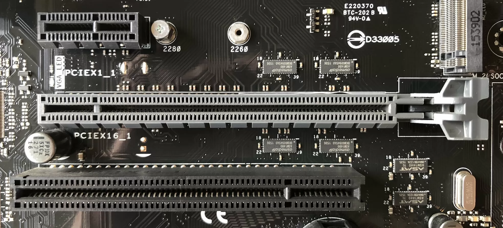
The image below shows 3 sockets: the top two are PCI Express, while the bottom one is a much older system called PCI (related to PCIe, but a lot slower). The little one at the top is labelled PCIEX1_1 because it is a single lane socket; the one below it is a 16 lane socket.
If you scroll back up and look at the whole motherboard again, you can see that there are:
2x PCI Express 1 lane sockets
3x PCI Express 16 lane sockets
2x PCI sockets
But if the CPU's controller only has 16 lanes, what's going on? First of all, only PCIEX16_1 and PCIEX16_2 are connected to the CPU - the third one, and the two single lane sockets are connected to another processor on the motherboard (more about that in a moment). Secondly, if both sockets were filled with devices that use 16 PCIe lanes, then the CPU will only dedicate 8 lanes to each.
This is the case of all CPUs today; they have a limited number of lanes, so as more devices get connected to the CPU, each one gets a smaller number of lanes to work with.
Different CPU and motherboard configurations have their own way of handling of this. For example, Gigabyte's B450M Gaming motherboard has one PCIe 16 lane socket, one PCIe 4 lane socket and a M.2 socket that uses 4 PCIe lanes. With only 16 lanes available from the CPU, using any two sockets will force the larger x16 one to be capped to 8 lanes.
So what kind of things use those sockets? The most common choices are:
16 lanes = graphics card
4 lanes = solid state drives (SSD storage)
1 lane = sound cards, network adapters
You can see the difference between the connectors in the image above. The graphics card sports the longer 16 lane one, compared to the sound card's little 1-lane setup. The latter has far less data to transfer than the former, so it doesn't need all those extra lanes.
In our motherboard example, like all others, has lots more sockets and connections to manage, and so the CPU gets a helping hand from another processor.
Let's head south and cross the bridge
If we go back 15 years or so, and look at motherboards from that era, there were two additional chips built into them to support the CPU. Together, they were called a chip set (usually concatenated to chipset), and individually they were called the Northbridge (NB) and Southbridge (SB) chips.
The former handled the system memory and graphics card, the latter processed the data and instructions for everything else.
The above image, of an ASRock 939SLI32 motherboard, clearly shows the NB/SB chips - they're both hidden under aluminum heatsinks, but the one closest to the CPU socket in the middle of the image is the Northbridge. A few years after this product was around, both Intel and AMD released CPUs that had the NB integrated into the central processor.
The Southbridge, though, has remained separate and is likely to be so for the foreseeable future. Interestingly, both CPU manufacturers have stopped calling it the SB and often refer to it as the chipset (Intel's proper name for it is the PCH, platform controller hub), even though it's just a single chip!
On our more modern example from Asus, the SB is also covered with a heatsink, so let's pop it off and have a look at the extra processor.
This chip is an advanced controller, handling multiple types and numbers of connections. Specifically, it's an Intel Z97 chipset and offers the following features:
8 PCI Express lanes (version 2.0 PCIe)
14 USB ports (6 for version 3.0, 8 for version 2.0)
It also has an integrated network adapter, an integrated sound chip, a VGA display output, and a whole host of other timing and controlling systems. Other motherboards will have more basic/advanced chipsets (providing more PCIe lanes, for example) but in general, most chipsets offer the same kind of features.
For this particular motherboard, this is the processor that handles the single lane PCIe slots, the third 16 lane slot, and the M.2 slot. Like many newer chipsets, it handles all of these different connections by using a set of high speed ports that can be switched to PCI Express, USB, SATA, or networking, depending on what is connected at the time. This, unfortunately, places a limit on how many devices plugged into the motherboard, despite all those sockets.
In the case of our Asus motherboard, the SATA ports (used to attach hard drives, DVD burners, etc) are grouped as shown above because of this limitation. The block of 4 ports in the middle use the chipset's standard USB connections, whereas the two on the left use some of these high speed connections.
So if you use the ones on the left, then the chipset will have fewer connections for other sockets. The same is true for the USB 3.0 ports. There is support for up to 6 devices, but 2 of these ports will also eat into the high speed connections.
The M.2 socket, used to connect SSD storage, uses the fast system, too (along with the third 16 lane PCI Express slot on this motherboard); however, on some CPU/motherboard combinations, the M.2 sockets connect directly to the CPU, as many newer products have more than 16 PCIe lanes to distribute and use.
Along the left hand side of our motherboard, there is a row of connectors generally called the I/O set (input/output) and in this instance, the Southbridge chip (or chipset) only handles a few of them:
VGA connector - for older/cheaper monitors (top middle)
USB 2.0 ports - black in color (bottom left)
USB 3.0 ports - blue in color (bottom middle)
The CPU's integrated graphics processor handles the HDMI and DVI-D sockets (bottom middle) but the rest are managed by additional chips. Most motherboard have a raft of extra little processors to manage all kinds of things, so let's have a look at some of those.
Additional chips for additional help
CPUs and chipsets have a limit to what they can support or connect to, so most motherboard manufacturers offer products with extra features, thanks to the use of other integrated circuits. This might be to provide extra SATA ports, for example, or provide connections for older devices.
The Asus motherboard we've been looking at is no different. For example, the Nuvoton NCT6791D chip handles all of the little connectors for fans and the temperature sensors built into the board; the Asmedia ASM1083 processor next to it manages the two legacy PCI sockets, because the Intel Z97 chip has no such capability.
Although Intel's chipset has a built-in network adapter, it uses some of those valuable high speed connections, so Asus added another Intel chip (an I218V) to manage the red ethernet socket we saw in the I/O set. The above image does no justice to how small this chip is: it's just 0.24 inches (6 mm) square!
The stadium-shaped silver metal thing is a type of quartz crystal oscillator – it provides a low frequency timing signal, for the networking chip to stay synchronized.
Something else that this motherboard offers as an extra is a chip to handle audio. Yes, the Intel chipset has its own integrated sound processor, but it's been bypassed for the same kind of reasons that Asus have added a separate networking chip and that most people add a graphics card to replace the integrated graphics processor in the CPU. In other words, the extra chip is just better!
Not all of the extra chips on the motherboard are about replacing integrated ones, many are there to manage or control the operation of the board in general.
These little chips are PCI Express switches and help the CPU and Southbridge manage the 16 lane PCIe connectors, when they need to distribute the lanes to more devices.
Motherboards with the ability to overclock CPUs, chipsets, and system memory are now commonplace, and many come with extra integrated circuits to manage this. In our example board, highlighted in red, Asus is using its own design called the TPU ('TurboV Processing Unit') that adjusts clock speeds and voltages to a fine level of control and adjustment.
The little Pm25LD512 device next to it, highlighted in blue, is a flash memory chip that stores the clock and voltage settings when the motherboard is powered off, so you don't have to redo them, every time you power up the PC.
Every single motherboard has at least one flash memory device, though, and this is for storing the motherboard's BIOS (the basic hardware initialization operating system that gets everything going before loading Windows, Linux, macOS, etc).
This Winbond chip is just 8 MB in size but that's more than enough to hold all of the software needed. This kind of flash memory is designed to use very little power when in use and hold onto its data for decades.
When you switch on the PC, the contents of the flash memory are copied directly to the CPU's cache or system memory, and then run from there, for maximum performance. However, the one thing that this memory can't hold onto is time.
This motherboard, like every other one around, uses a CR2032 cell to power a simple timing circuit, that keeps track of the data and time for the motherboard. Of course, the power of a cell doesn't last forever and once it's flat, the motherboard will default to a starting time/date in the flash memory.
And speaking of power, there are more connectors for that, too!
Bring me the power, Igor!
To provide the voltage and current required to run the motherboard and many of the devices attached to it, the computer's power supply unit (PSU) will have a number of standard connectors for this purpose. The main one is a 24-pin ATX12V version 2.4 socket.
The amount of current that can be drawn from the pins depends on the PSU, but the voltages are industry set to +3.3, +5, and +12 volts.
The bulk of the current for the CPU is drawn off the 12 volt pins, but for modern high-end systems, it's not enough. To get around this problem, there is an additional 8-pin power connector that provides another four set of 12V pins to be used.
The connectors from the PSU have color coded wires to help identify what each wire is for, but the sockets on the motherboard don't tell you very much. Here's a diagram for the two power sockets:
The +3.3V, +5, and +12V lines supply power to the various components on the motherboard itself, and also powers the CPU, DRAM, and any devices plugged into the extension sockets such as the USB or PCI Express slots. Anything using the SATA ports need power directly from the PSU, though, and PCI Express sockets can only provide up to 75W. If the device needs more juice than that – lots of graphics cards do – then they'll need to be hooked up to the PSU directly, too.
However, there's a larger problem than having enough 12V pins: CPUs don't run on that voltage.
For example, the Intel CPUs designed to run on this Asus Z97 motherboard run off voltages between 0.7 and 1.4 volts. It's not a fixed voltage, because today's CPUs vary how much voltage they're running on to save power and reduce heat; so when idling on the desktop, the CPU can tootle away with less than 0.8 volts. Then with all the cores fully loaded and working away, it rises to 1.4 volts or more.
Power supply units are designed to convert mains AC voltage (110 or 230, depending on the country) into fixed DC voltages, so additional circuits must be used to drop them lower and vary them as required. These circuits are called voltage regulation modules (VRMs, for short) and can be easily spotted on any motherboard.
Each VRM is typically comprises 4 components:
2x MOSFETs - high current switching transistors (blue)
1x inductor - also known as a choke (purple)
1x capacitor (yellow)
You can read more about how they work on Wikichip, but let's briefly go through a few things. Each VRM is usually called a phase and multiple phases are required, because one alone can't supply enough current for a modern CPU (our motherboard has 8 VRMs, called an 8-phase system).
The VRMs are usually managed by a separate chip, that monitors the device, and switches the modules as for the required voltage. These are called multiphase pulse width modulator controllers; Asus calls theirs an EPU! All of these things get quite hot when they're working away, so they're often covered by a metal heatsink to help dissipate the waste energy.
Even a standard desktop CPU, such as an Intel i7-9700K, can draw over 100A of current when fully loaded. VRMs are very efficient, but they can't change voltages without some losses; combined with the large current draw, and you have a good recipe for making things very toasty indeed.
If you look back up through this article, you'll see that there a couple of VRMs for the DRAM modules, too, but since they don't draw nearly the same amount of current as a CPU, they don't get as hot (and so don't need a heatsink).
Those annoying fiddly bits!
The last connectors to talk about are the ones for controlling the basic operation of the motherboard and attaching additional devices or extensions. The image below shows a basic set of control, lights, and speaker pins:
Here we have:
1x soft power switch
1x reset switch
2x LED connectors
1x speaker connector
The power switch is 'soft' because it doesn't actually switch the motherboard on and off; instead, circuits on the board monitor the voltage across the two pins for the switch and when they are connected together (i.e. short circuited), the motherboard will either power on or off, depending on its present status. The same applies for the reset switch, except here the motherboard will always power off, and then immediately back on again.
Strictly speaking, the reset switch, LED and speaker connectors aren't absolutely necessary but they do help to provide basic control and information about the board.
Most motherboards have a similar array of extra connectors as shown above - from left to right, we have:
Audio panel connector - if the PC case has headphone/microphone jacks built into it, then they can be connected to the onboard sound chip
Digital audio connector - same as the other audio connector, but for S/PDIF
BIOS clear jumper - this allows the BIOS to be reset to default factory settings. There is also a thermal probe connector hidden behind it
Trusted Platform Module connector - used to help make the motherboard and system more secure
Serial Port (COM) connector - an ancient interface. Anyone use these at all? Anyone? Bueller?
Also plastered across this motherboard, but not shown, are connections for fans and extra USB ports. Not every motherboard will sport all of these but many do.
Connecting all of this together
Before we finish our look at the anatomy of a motherboard, let's briefly talk about how all of these devices and connectors are wired together. We've already mentioned traces but what exactly are they?
Put simply, they're small strips of copper. You can see some of them below painted black for better looks. However, this is only a small number of thousands of traces required. The rest are sandwiched between the multiple layers that make up the full circuit board.
Simple, cheap motherboards might only have 4 layers, but most today have 6 or 8 – adding more layers doesn't automatically make things better, though. It's about how many traces there are in total and how important it is to keep them separated and insulated to prevent them interfering with each other.
Motherboard designers use software to help them work out the best routes for all of these traces; experienced engineers will often tweak the layout, though, based on evidence from practical investigations. What the following video to get a sense of how the routing of traces in printed circuit boards (PCBs) gets processed.
Since motherboards are just large PCBs, it is possible to build your own and if want an idea on how to go about this, then have a read of this excellent tutorial of fabricating a PCB.
It's a different story for producing motherboards on an industrial scale, of course, so to get a sense of how complex all of this is, check out the two videos below. The first one is how circuit boards, in general, are designed and manufactured; the second one shows you the main assembly process of a typical motherboard. Enjoy!
Final words
So there you have it: a dissection of a modern desktop PC motherboard. They're big, complex circuit boards, packed with processors, switches, connectors, and memory chips. There's so much interesting technology in use, but we often forget about them, as they sit in the cases.
But hopefully you've picked up things along the way and, more importantly, you've got a stack of questions you want to ask about yours! Well, send them our way, using the comments section or visit the CPU & Motherboard section of our forum.
As you know we regularly review the latest motherboards out there and offer our thoughts as to what's best for a given budget and platform. Stay tuned for more anatomy lessons!